Rochester Institute of Technology (RIT) Baker Hall – Phase 1
Overview
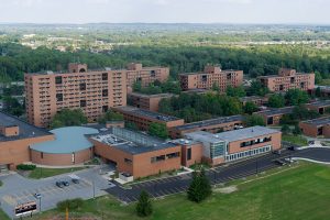
Like many colleges and universities throughout the US, Rochester Institute of Technology (RIT) has many buildings that are half a century older or more. Over time and decades of use, these buildings have grown antiquated and are in need of updating and repair and renovation.
Residence halls are densely occupied spaces with students living in these halls 9-10 months out of the year. The living spaces are put to the test each year with a new round of students coming for the upcoming school year and after decades of use and abuse, the sleeping rooms and utilities ultimately succumb to the point at which improvement and upgrades must be implemented.
Most of RIT residence halls were constructed in the late 60’s and it has been approximately 20 years since the last overall occurred for these buildings. The scope of the renovations previously addressed layout, lighting, and other cosmetic solutions.
Beyond the look, fit, and usability, the HVAC mechanical systems are due for upgrades.
THE PLAN
RIT has put into motion a multi-year, multi-million dollar renovation project scope to address the many items of need that have crept in since the last renovation work over two decades ago. The scope of spaces to address as part of this renovation includes work on all 13 residence halls including 1,800 rooms and 400 bathrooms. The majority of the renovation work will address, lighting, upgraded kitchenettes, flooring, ceiling, painting, doors, and improved bathroom facilities.
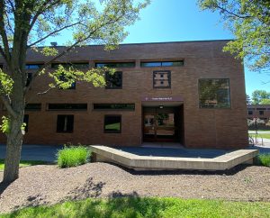
A major item for eight of the 13 dorms will be the addition of air conditioning in dorm rooms and other living spaces. The renovation work at RIT initiated last summer at Baker Hall A & B, with continued work this summer at Baker Hall. RIT has laid out a plan to phase the other hall upgrades over the next 2 years with the completion to occur later summer, into fall of 2025.
THE SOLUTION
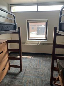
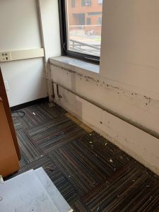
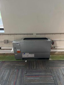
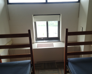
The scope of Baker Hall included the addition of air conditioning in dorm rooms which were previously only served with heating via radiant, floor mounted fin tube heating. The approach selected for delivering cooling and heating to these spaces was what is called a fan coil unit or FCU. A fan coil unit FCU) is designed to take a mix of return air and fresh outside air, and heat or cool via a coil device and then distribute the treated air with the onboard fan to satisfy the thermostat setting per the occupant’s comfort levels.
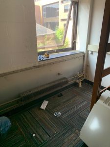
Typically the fan coil is housed on the floor within its factory cabinet enclosure. However, often times, in a typical installation arrangement, controls, piping, and electrical items are exposed to space and occupants. Over time, those devices can get damaged and shorten the useful lifespan of the equipment. To provide an increased level of protection for the FCU equipment, and to create a uniform fit and finish for the students, RIT and its design team consultants developed a plan for a complete wall-to-wall enclosure. These Fan Coil Enclosures (FCE) would be constructed to fully cover the FCU and the associated water piping feeding the FCU and the associated controls and electrical devices.
Another reason for developing a wall-to-wall enclosure in lieu of simply enclosing the FCU with a factory panel was to protect the water piping being routed to the FCU. As you can see in the photo to the right of the FCU, the copper tubing enters the room horizontally, not vertically in close proximity to the FCU where a factory housing cover would typically conceal the piping. The fan coil enclosure, FCE, needed to be a) rigid, to withstand the demands of dorm living, b) flexible to install across varying styles and dimensions of rooms, c) allow for repeatable installation and d) provide a uniform look from wall-to-wall and from room-to-room and floor-to-floor.
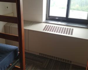
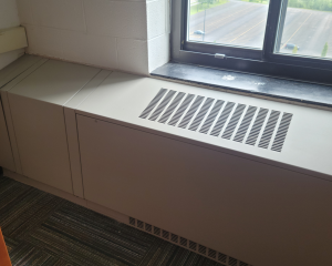
What Carson Solutions designed was a systematic assembly that allowed for perimeter support while integrating field adjustability and flexibility suitable for varying dimensioned rooms. The FCE design also included interstitially spaced mullions to increase rigidity across the top and front panels. Although the entire FCE was constructed of heavy, 14 ga, sheet metal, additional mullions as shown greatly increase the ruggedness of the structure. The top panel was specifically designed with a slope to help direct airflow into the room but to eliminate the FCE as a ledge that could be damaged by standing or placing items. Notice no support mullion is positioned in the area of the installed FCU. The design of the FCE panels is specifically intended for access to the FCU for routine maintenance and operation adjustments should they be needed.
Where
Rochester, New York
PROJECT TEAM
Construction Manager, Architect, & MEP Engineer:
Wendel Companies
Williamsville, NY
General Contractor
Christa Construction
Rochester, NY
Mechanical Contractor
Crosby-Brownlie
Rochester, NY
HVAC Equipment Representative
Guckian Energy Systems
Victor, NY
EQUIPMENT
• Fan Coil Unit – Superior Rex
• Fan Coil Custom Enclosure -Carson Solutions